Learn how to use the CGDI CG100X programmer to read EEPROM data without soldering. This guide provides step-by-step instructions, including establishing connections, locating the pin diagram, and utilizing the operation interface. Download the CG100X EEPROM support list for comprehensive compatibility.
Guidance on using CGDI CG100X to read EEPROM without soldering.
Devices and accessories required:
CG100X programmer
EEPROM Adapter
EEPROM Clip
ECU
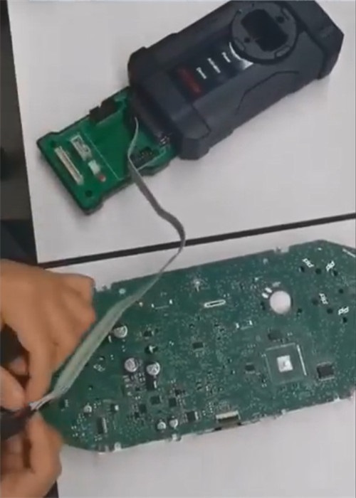
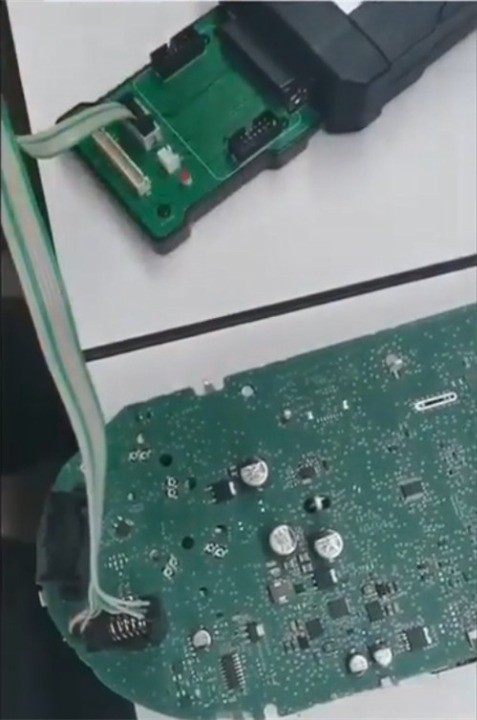
Establish the necessary connections for reading EEPROM
Plug EEPROM Adapter into CG100X programmer
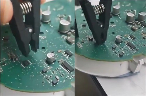
Connect one side of EEPROM Clip to EEPROM Adapter
Connect the other side of EEPROM Clip to ECU chip
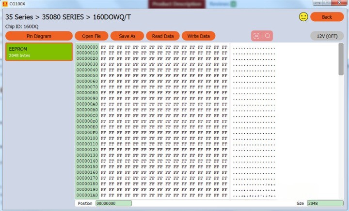
Locating pin diagram
Before proceeding, it's crucial to locate the pin diagram for the specific chip. Fortunately, CG100X software provides an easy-to-access pathway to find the pin diagram:
Select Programmer > Manufacturer > Series > Chip
Double-click on the selected chip or click Next to proceed.
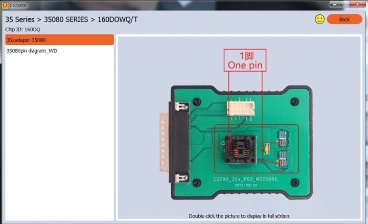
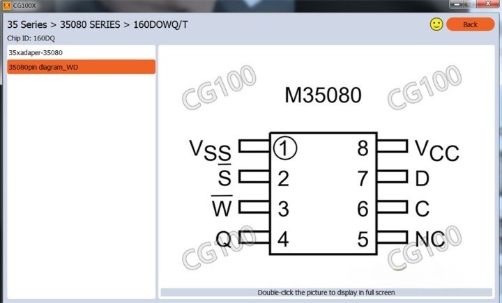
In the Pin Diagram section, you will find the detailed pin layout. For example, if you're using a 35 series 35080 160DOWQ/T chip, follow the path: Select 35 Series > 35080 SERIES > 160 DOWQ/T > double-click or click Next.
Navigate to the operation interface
Once you have completed the above steps, you will be presented with the operation interface. This interface allows you to control the reading and writing processes. To make the most of it, follow these guidelines:
Click on "Pin Diagram" option to access the required adapter and pin diagram information.
Review the pin diagram to ensure the correct adapter is selected and properly connected.
Select the relevant option from the interface to initiate the reading or writing of EEPROM data.